



















Skip to product information
1 of 51

Wired In

DIY Custom Keyboard Cable Kit

DIY Custom Keyboard Cable Kit

Regular price $24.00
Regular price Sale price $24.00
Sale Sold out
Shipping calculated at checkout.
5.0 / 5 · 2 reviews
// loading kit builder…
View full details
// DIY CABLE KIT · SOLDER-IT-YOURSELF
Product Description
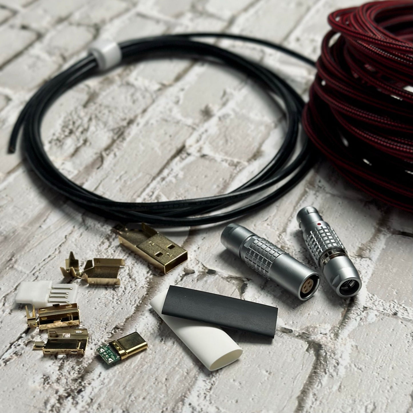
Everything you need to hand-build one sleeved mechanical keyboard cable, configured to taste. Choose your cable type and length, sleeve color, optional TechFlex overbraid, an optional detachable FEMO connector, heat-shrink color, and extras — then solder it together. Requires soldering and basic DIY know-how; all sales final.
CONFIGURE

Built your way

Pick cable type, length, sleeve color, TechFlex, connector, and heat shrink — priced live as you build.

SOLDER

Hands-on assembly

Ships as components with housings and PCBs. Soldering and basic DIY know-how required.

MODULAR

Optional detachable

Add a FEMO 0B or 1B push/pull connector for a fully detachable, modular cable.

Specifications
// WIRED INWI-KIT-DIY
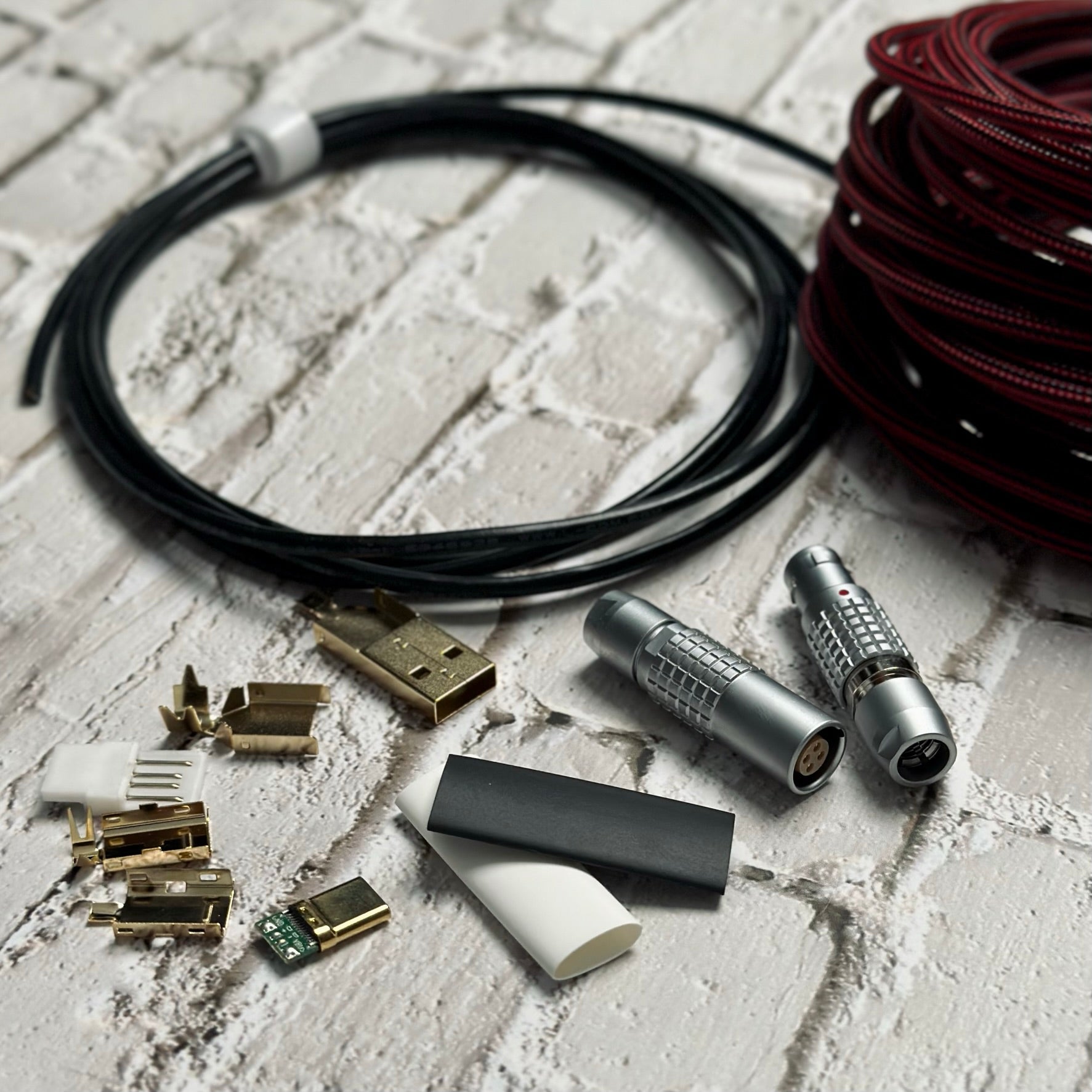
In the box USB-A/C connector set (housings + PCBs), bulk USB cable, MDPC-X sleeving, two heat-shrink slices
Cable types USB-A to C · USB-C to C · USB-A to Mini
Length 4 ft standard, up to 8 ft
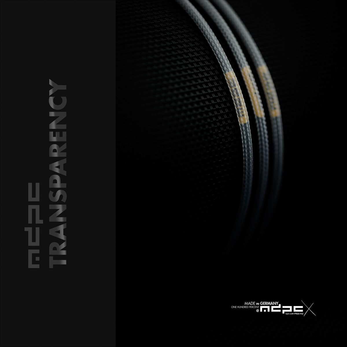
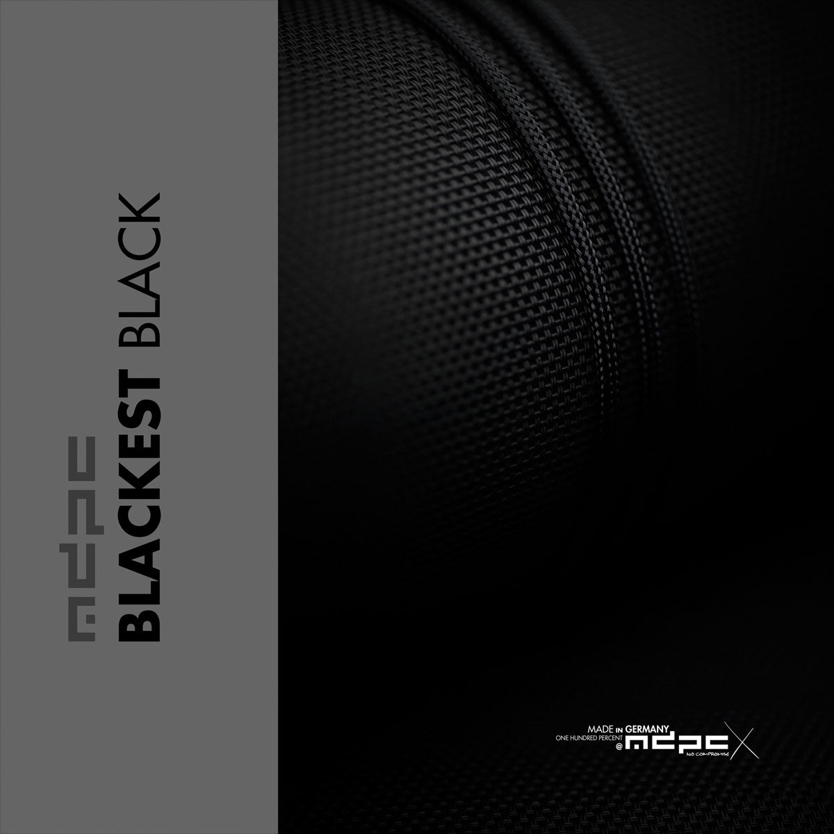
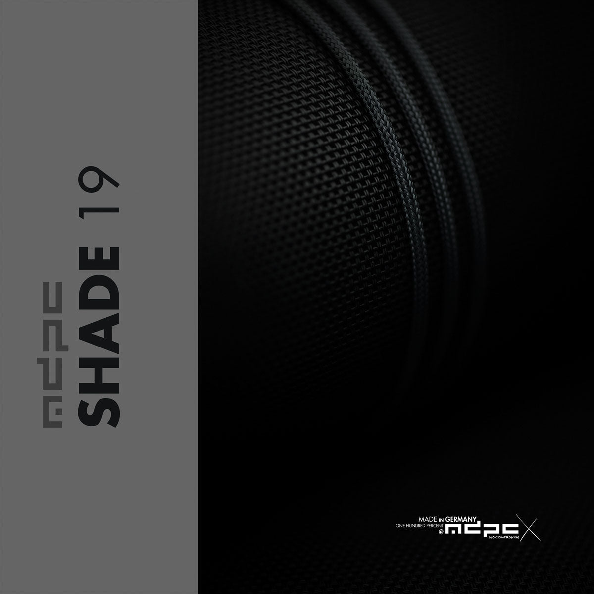
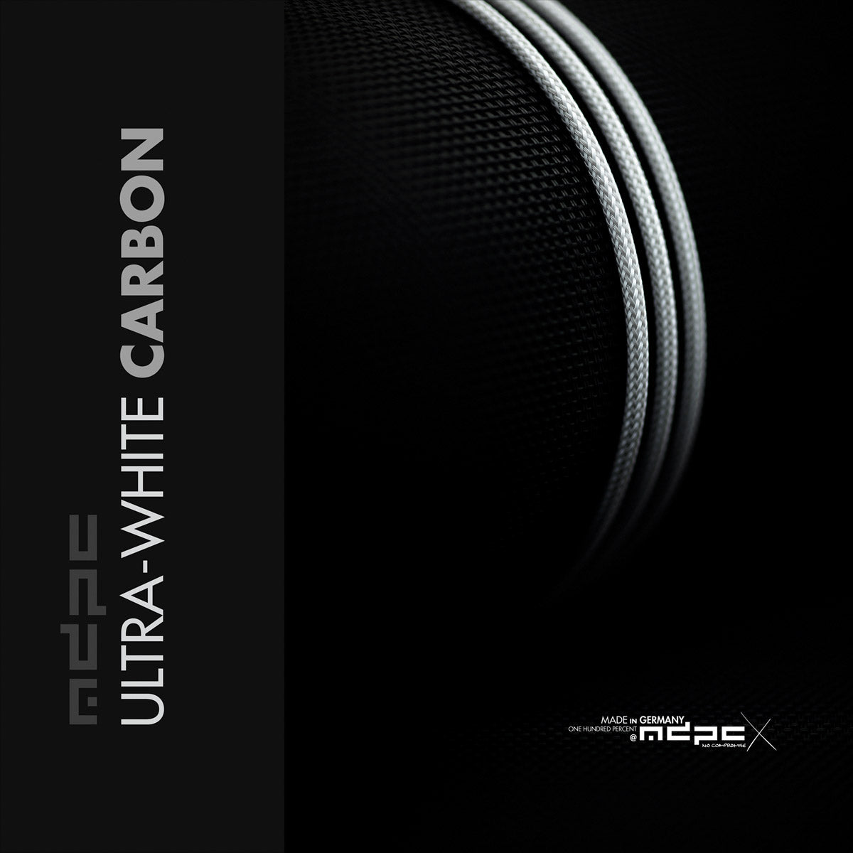
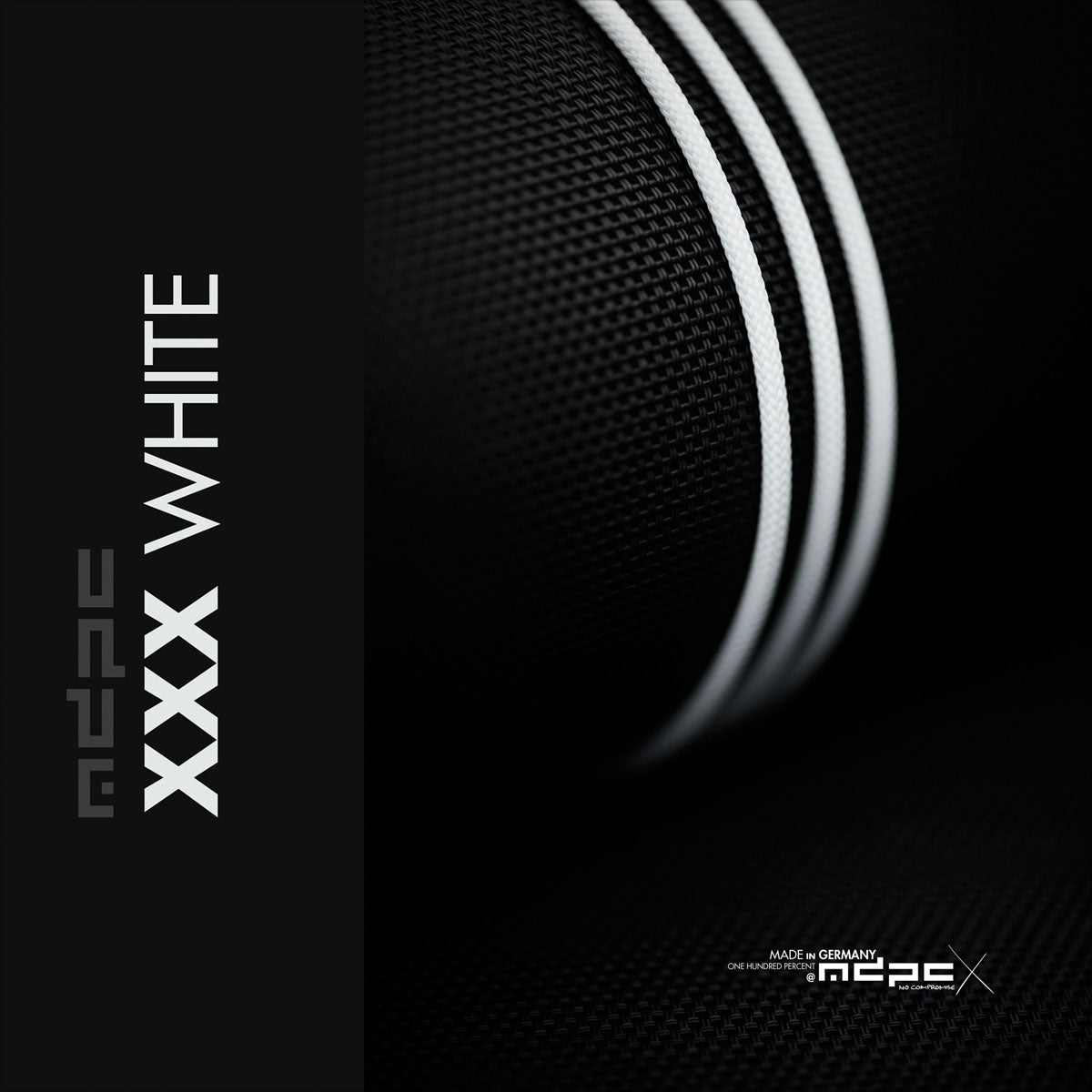
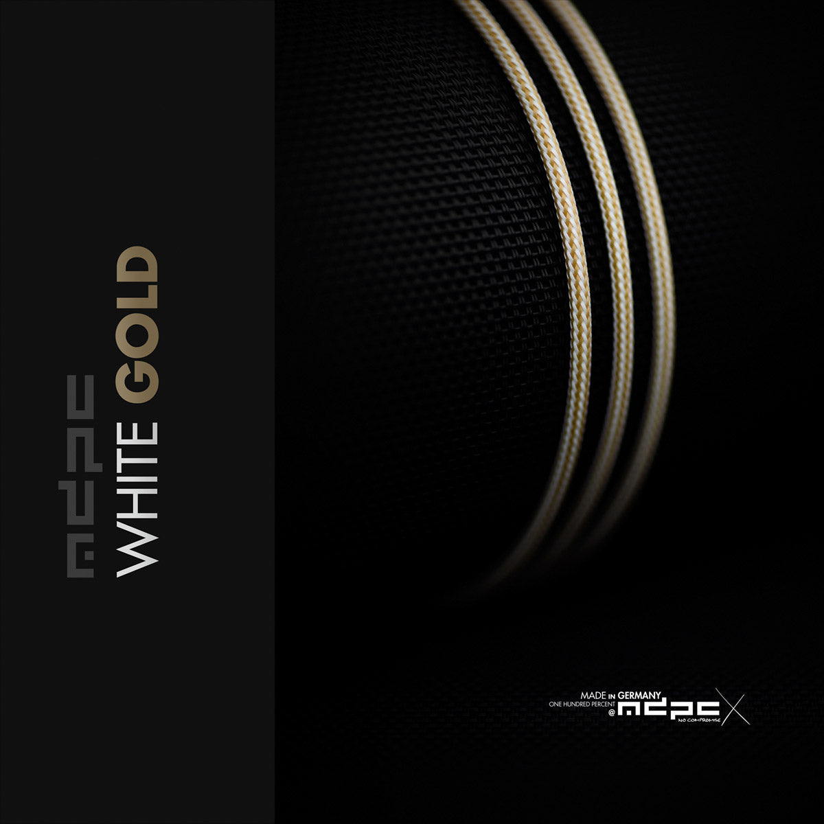
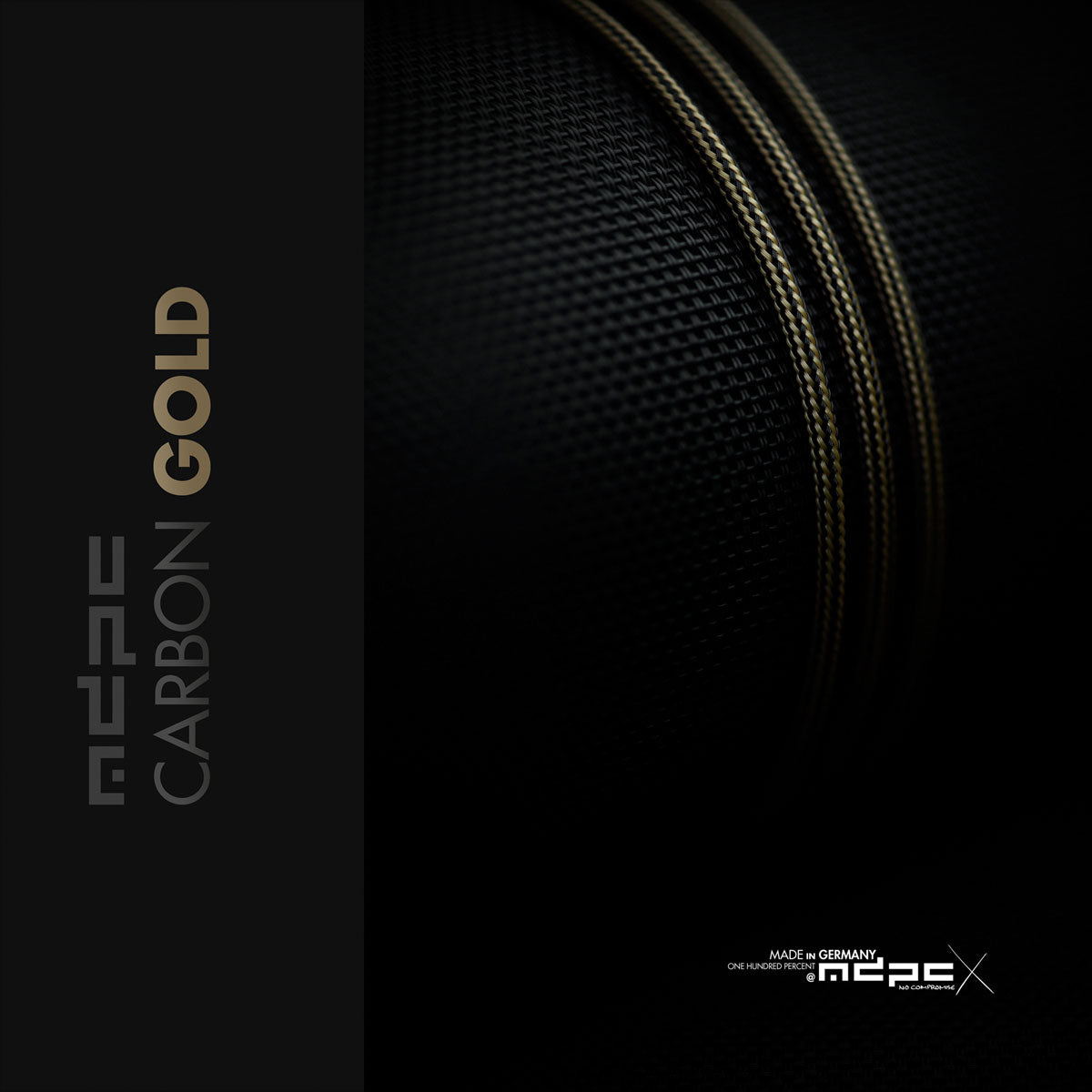
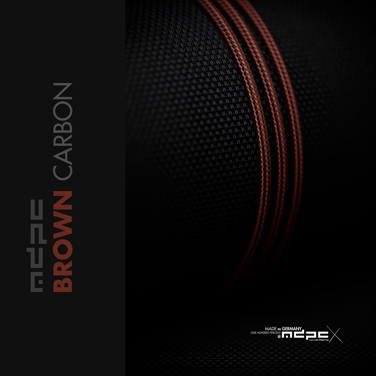
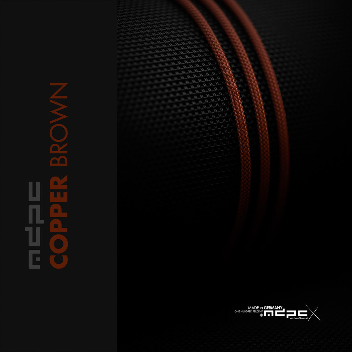
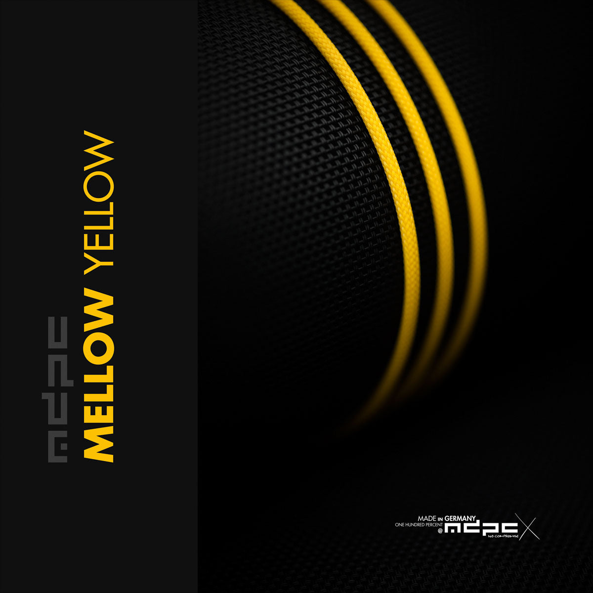
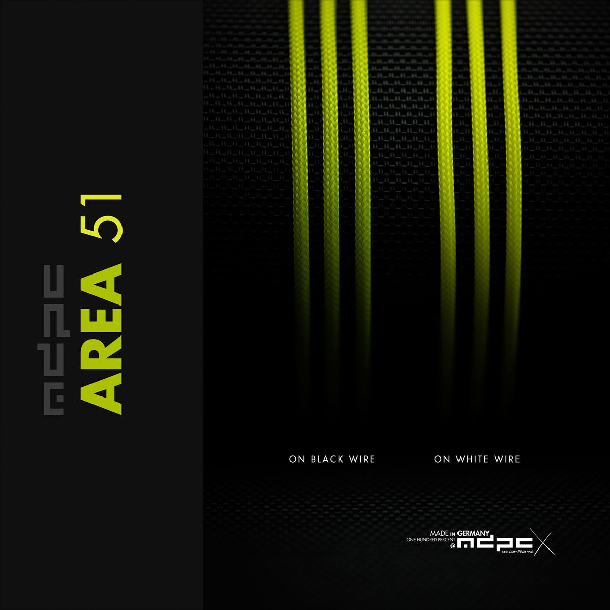
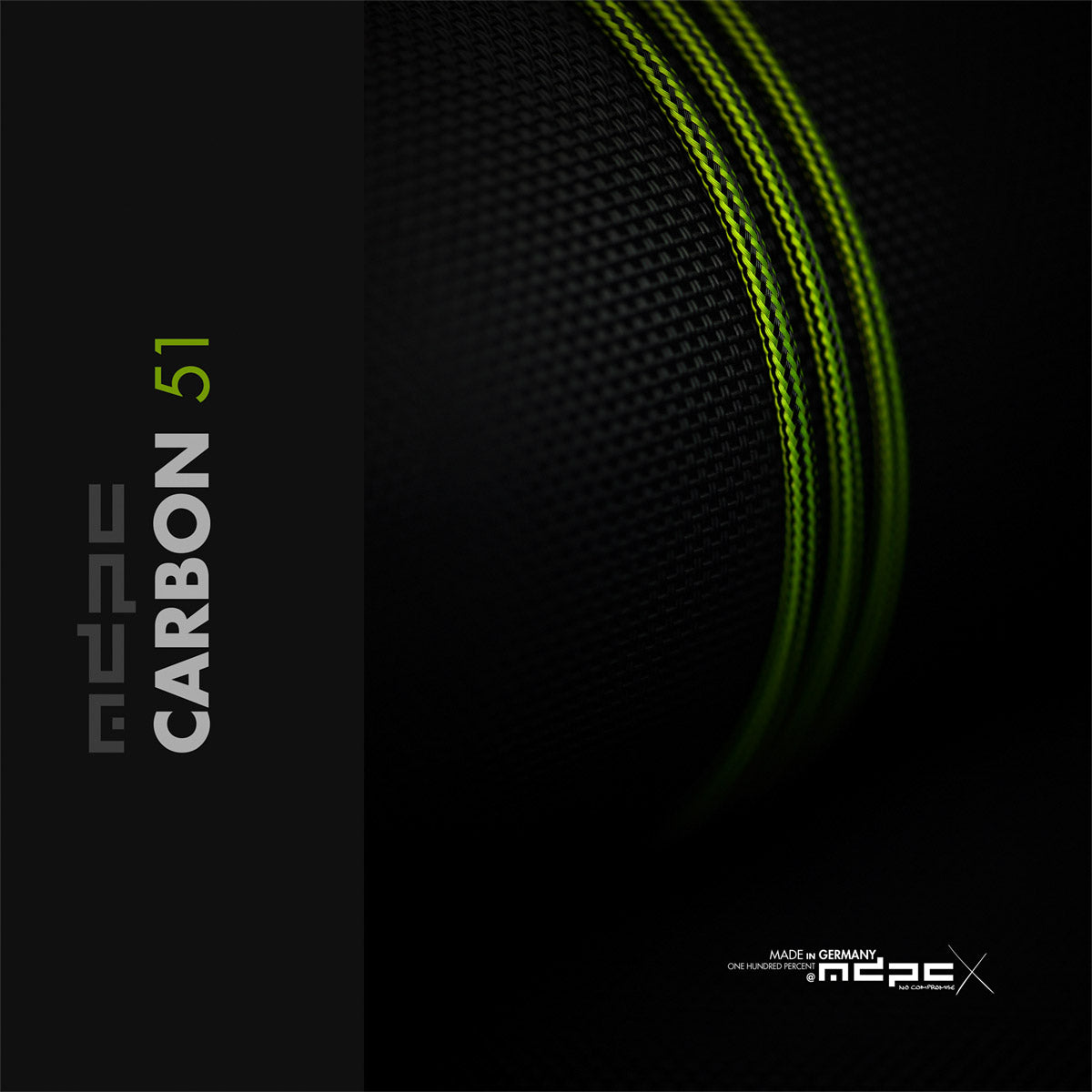
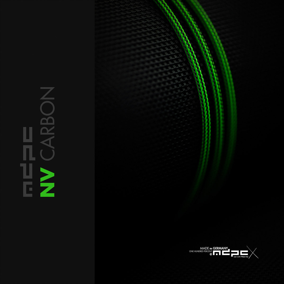
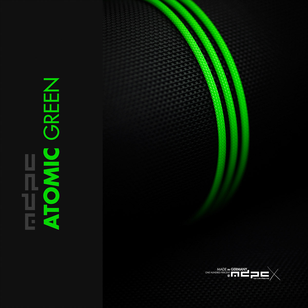
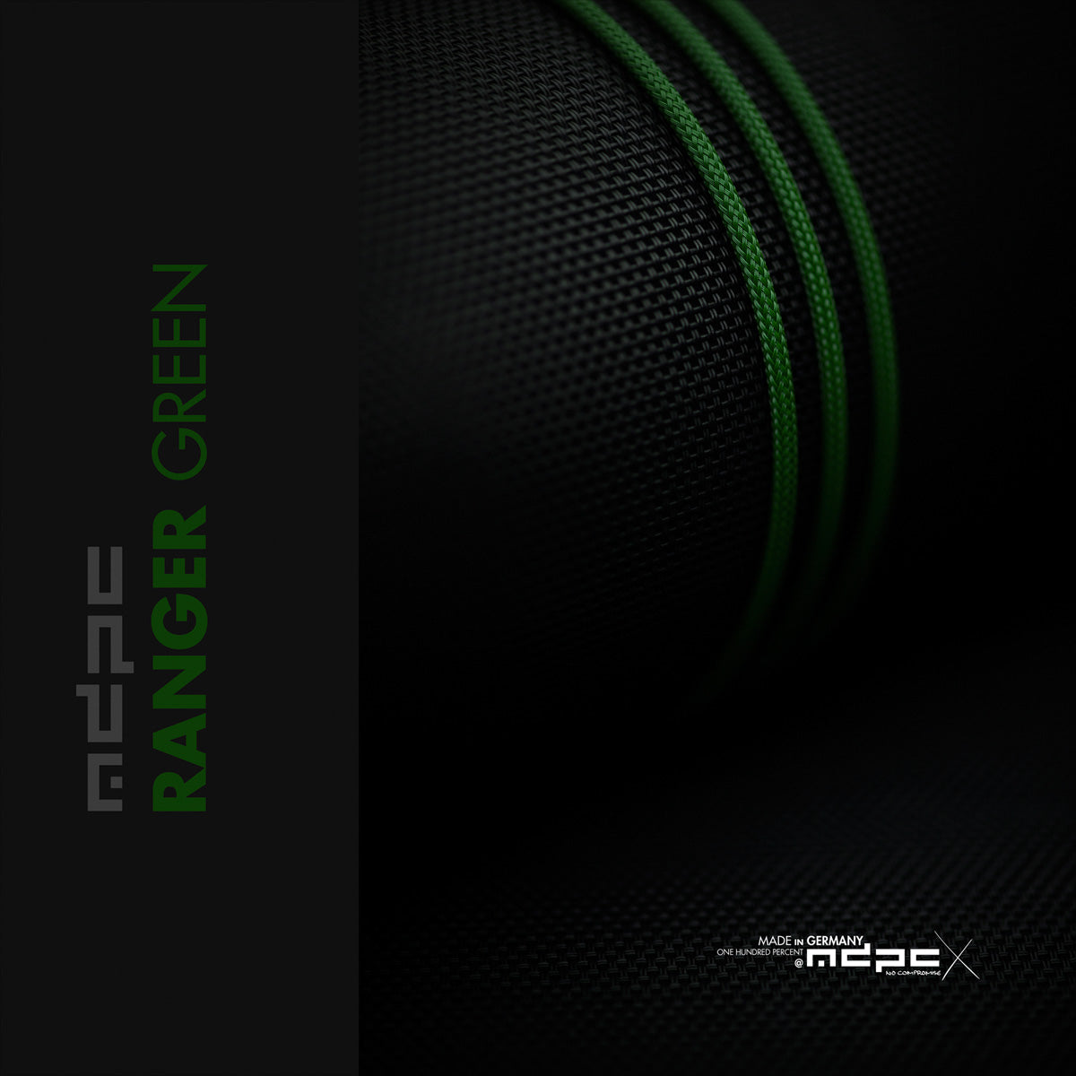
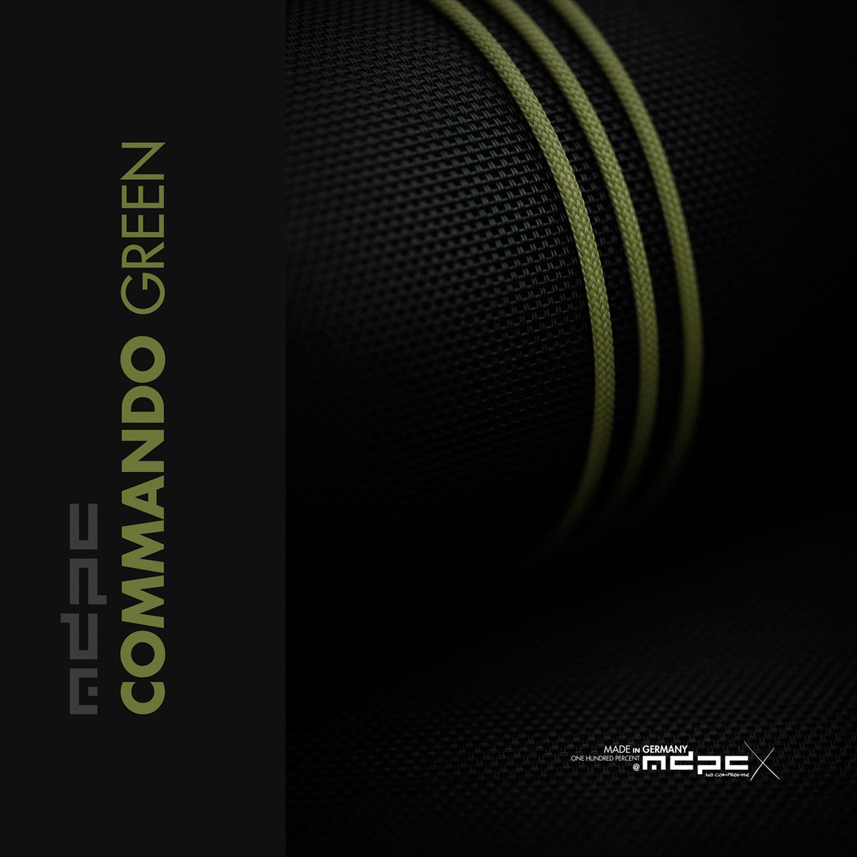
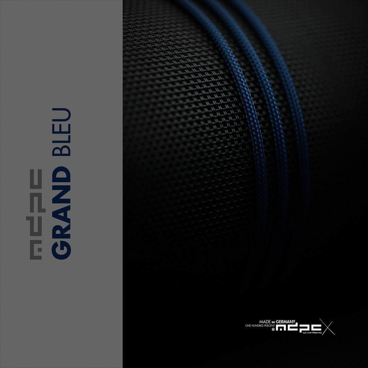
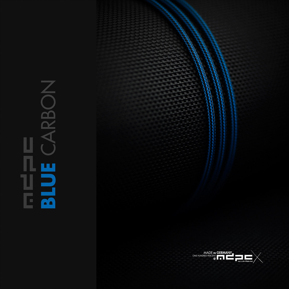
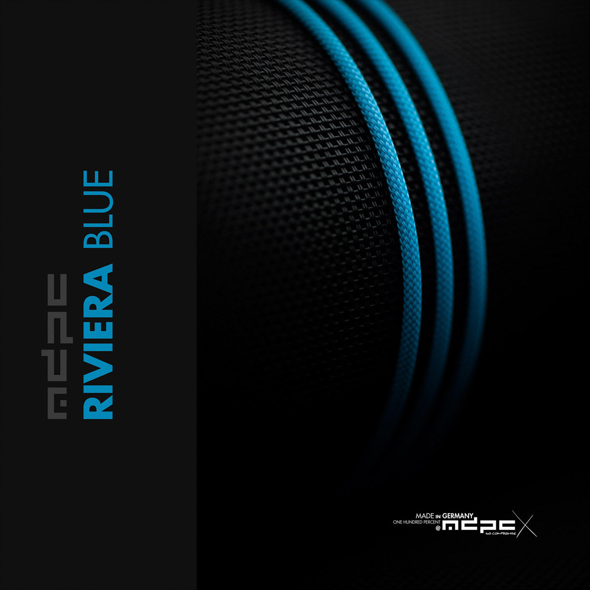
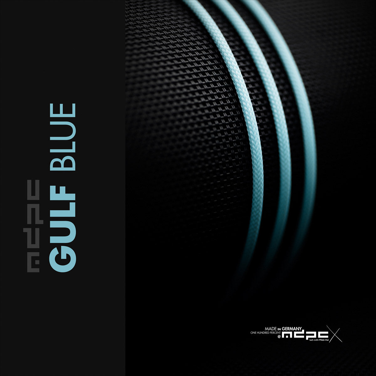
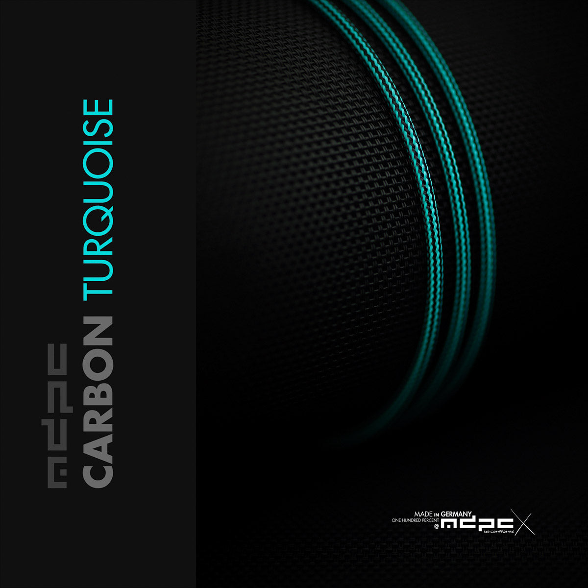
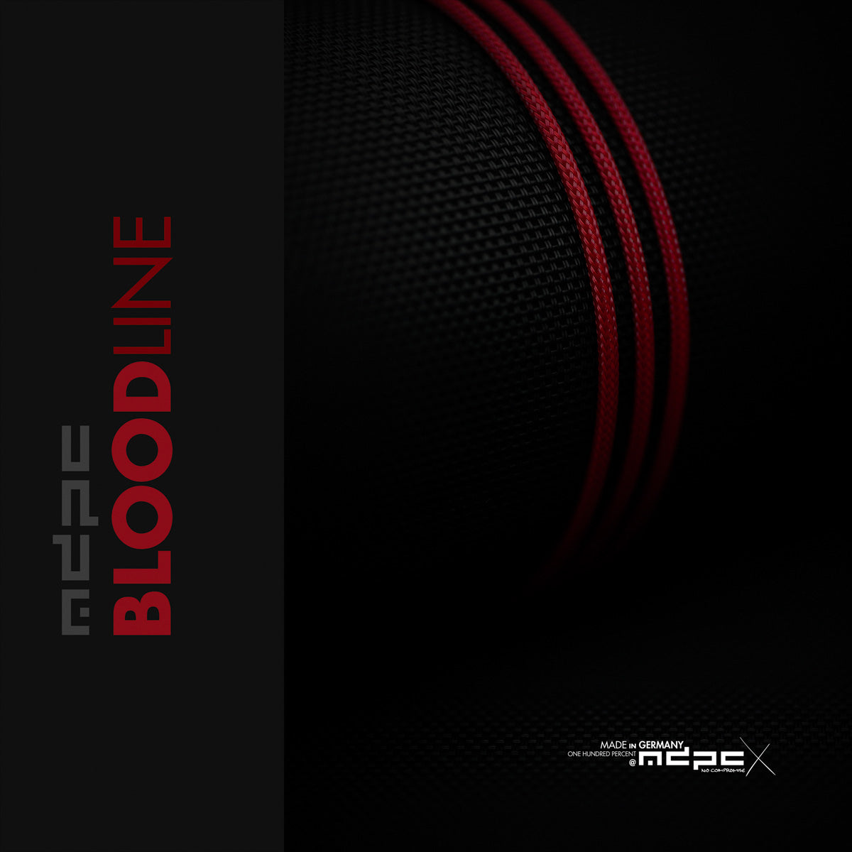
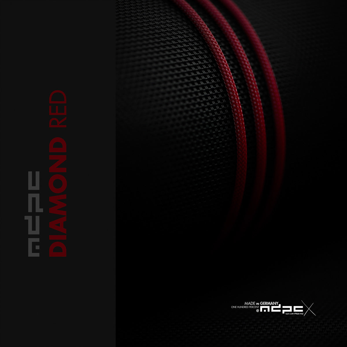
Sleeving MDPC-X XTC — 48 colorways
Add-ons TechFlex overbraid · FEMO detachable connector · spare USB set · Kester solder
Skill level Intermediate — soldering required
Soldering & Pinout

Wire Color Standard

1GNDBlack
2D+Green
3D−White
4PWR (VBUS)Red
5CC / GND2Blue
6PWR2Yellow
Pin numbers follow the numbered 1B insert. Pins 1–4 are the USB 2.0 standard and never change. Pin 5 (blue) and pin 6 (yellow) hold a fixed wire color — their function depends on the configuration below. D+ / D− are a single differential pair and are never doubled.

How USB-C Detection Works (the CC line)

A USB-C device won't power on just because 5 V is present — it has to detect a valid partner through the CC (Configuration Channel) line first. That's why a bare 4-pin cable can be hit-or-miss on USB-C.

USB-A → USB-C: the A host has no CC pin, so the cable must present a 56 kΩ resistor from CC to VBUS so the C device sees a legacy host and draws power.

USB-C → USB-C: the host watches CC for the device's 5.1 kΩ pull-down (Rd). The cable must carry CC through (or the connector must supply Rd onboard) or the host never enables VBUS/data.

CC1 vs CC2: USB-C is reversible — only one CC is live per orientation, so we wire a single line labeled simply CC.

4-PIN · USB 2.0 Standard
USB-A→C · USB-C→C
1
GND
Black
2
D+
Green
3
D−
White
4
PWR
Red
PinSignalWireNotes
1GNDBlackGround.
2D+GreenData pair.
3D−WhiteData pair.
4PWRRed+5 V VBUS.
USB-C→C as 4-pin only works if the connector supplies CC onboard (see note below). On USB-A→C, the C end still needs the 56 kΩ CC pull-up to be reliable.
Optional — proper USB-C shield: run GND / D+ / D− / PWR on the front of the USB-C PCB and land the braided shield as a second ground on the rear pad.
5-PIN · adds CC
USB-A→C · USB-C→C (non-fast-charge)
1
GND
Black
2
D+
Green
3
D−
White
4
PWR
Red
5
CC
Blue
PinSignalWireNotes
1–4GND · D+ · D− · PWRBlk/Grn/Wht/RedStandard USB 2.0 (as above).
5CCBlueA→C: 56 kΩ pull-up CC→VBUS (legacy-host detect).   C→C: carry CC through for sink (5.1 kΩ Rd) detection.
The 5th pin is what lets a USB-C→C link be recognized — a 4-pin C→C often won't enumerate without it. Genuine LEMO has true 5-pin inserts; for non-genuine 5-pin, use a 6-pin insert and leave pin 6 empty.
6-PIN · Fast Charge
USB-C→C only
1
GND
Black
2
D+
Green
3
D−
White
4
PWR
Red
5
GND2
Blue
6
PWR2
Yellow
PinSignalWireNotes
1–4GND · D+ · D− · PWRBlk/Grn/Wht/RedStandard USB 2.0 (as above).
5GND2BlueSecond ground — doubled for current capacity.
6PWR2YellowSecond +5 V — doubled for current capacity.
Pins 5 & 6 double up ground and power for higher fast-charge current. At the device end, bond GND+GND2 → one ground and PWR+PWR2 → one +5 V. CC detection is handled by the resistor on the connector PCB.

Pin Cup Orientation

Looking at the solder cups with the keyway / red dot held up. The female face numbers clockwise from just right of center; the male face is its mirror (counter-clockwise from just left). The keyway is your reference — count from it every time.
4-PIN · dice-4
Female
Male
6-PIN · fast charge (even hexagon)
Female
Male
The keyway centerline sits between pins 1 and 6.
5-PIN · 6-pin insert, one cup empty
Female
Male
We use a 6-pin insert and leave pin 6 empty (dashed). ⚠ In male / reverse orientation it's easy to mis-fill — you are not filling every cup like a 4-pin, so count from the keyway each time.

Connector PCB Pads

Where each wire lands on the USB connector's own solder PCB. ⚠ Representative — pad order and labels vary by connector (PWR may read VCC / V+ / 5V; CC may read ID; some boards split GND/PWR to the reverse). Always solder to the labels printed on your PCB.
USB-A · 4 padsSolder side
USB-C · front pads (5-pin shown)Solder side
6-pin (fast charge): same front pads + GND2 (blue) · PWR2 (yellow) on the reverse, doubled for current. 4-pin omits CC — the onboard chip handles it.

CC Resistor — On the Connector

Our USB-C connectors carry the CC resistor on the connector's own PCB (confirmed on the fast-charge connectors — there's a small chip on the board). That's why a "4-pin" solder can still enumerate, and how the 6-pin handles detection while pins 5/6 do power.

If a build is inconsistent across machines, the CC resistor is the suspect — missing, wrong value, or a host that strictly enforces CC. To wire CC by hand instead: 56 kΩ to VBUS for A→C, 5.1 kΩ to GND on the C-sink end.

Requires soldering and basic DIY know-how. Verify polarity and continuity before first plug-in.
WIRED IN · USB Cable Solder Spec
Wiring standard — Rev. 2026